
HARDWARE
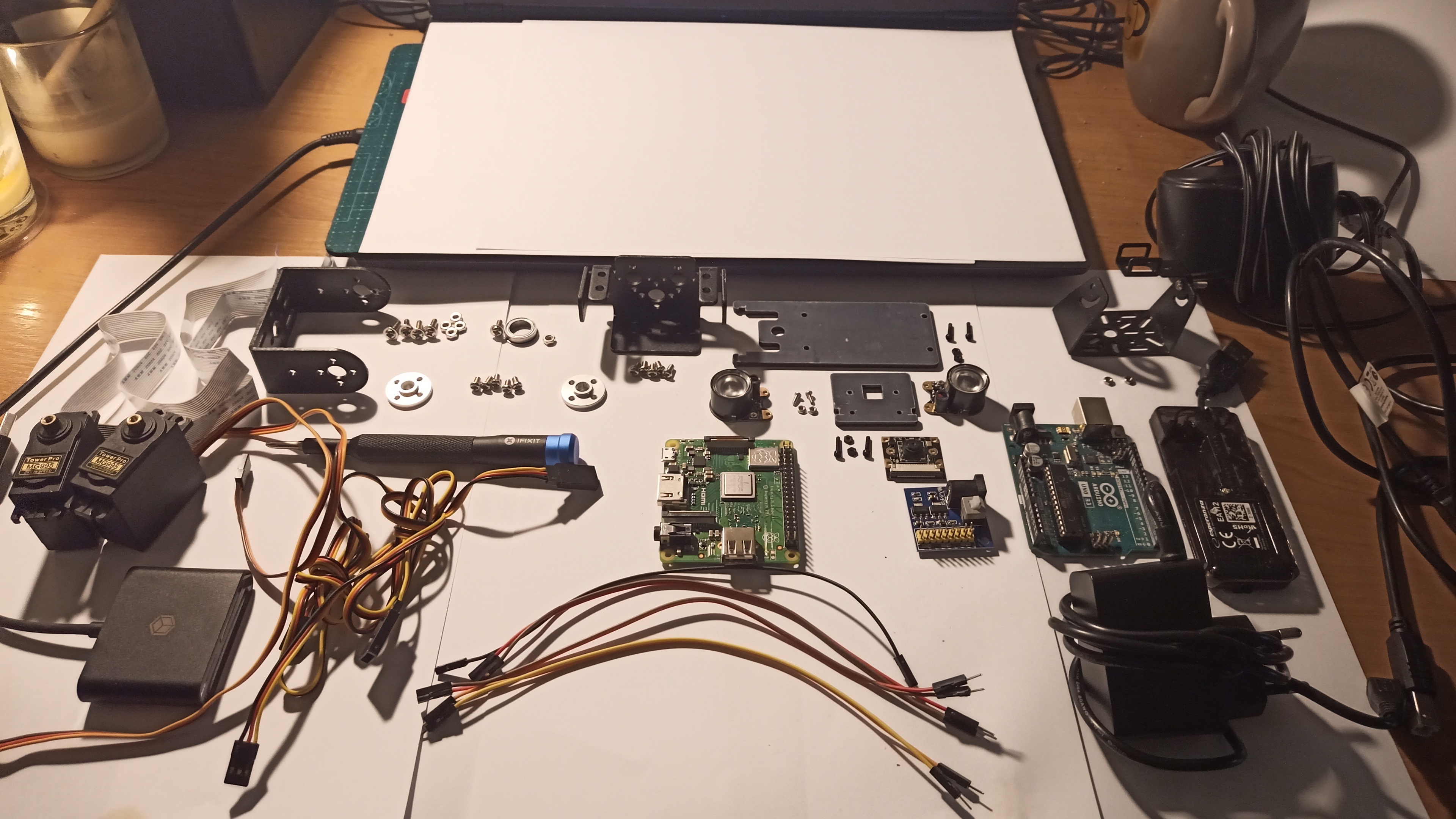
1) Required components: 2x TowerPro MG995 servo, aluminum Pan/Tilt Kit standard mount (lower and upper part), 2x aluminum round horn, 1x aluminum hoop, 2x servo extension cable, RPI camera mount, HD Night Vision E OV5647 5Mpx camera with IR illuminators , 60cm CSI tape, 5V power module, Raspberry Pi 3 A+, Arduino Uno (or Nano), 9V power supply, 5V power supply, USB A <> USB B cable, USB hub, cables, screws, nuts.
The exact list of all the sample components used below along with links can be found in documentation. Any materials and servos of any power can be used to build the structure, the project presented below is only an example.
The exact list of all the sample components used below along with links can be found in documentation. Any materials and servos of any power can be used to build the structure, the project presented below is only an example.
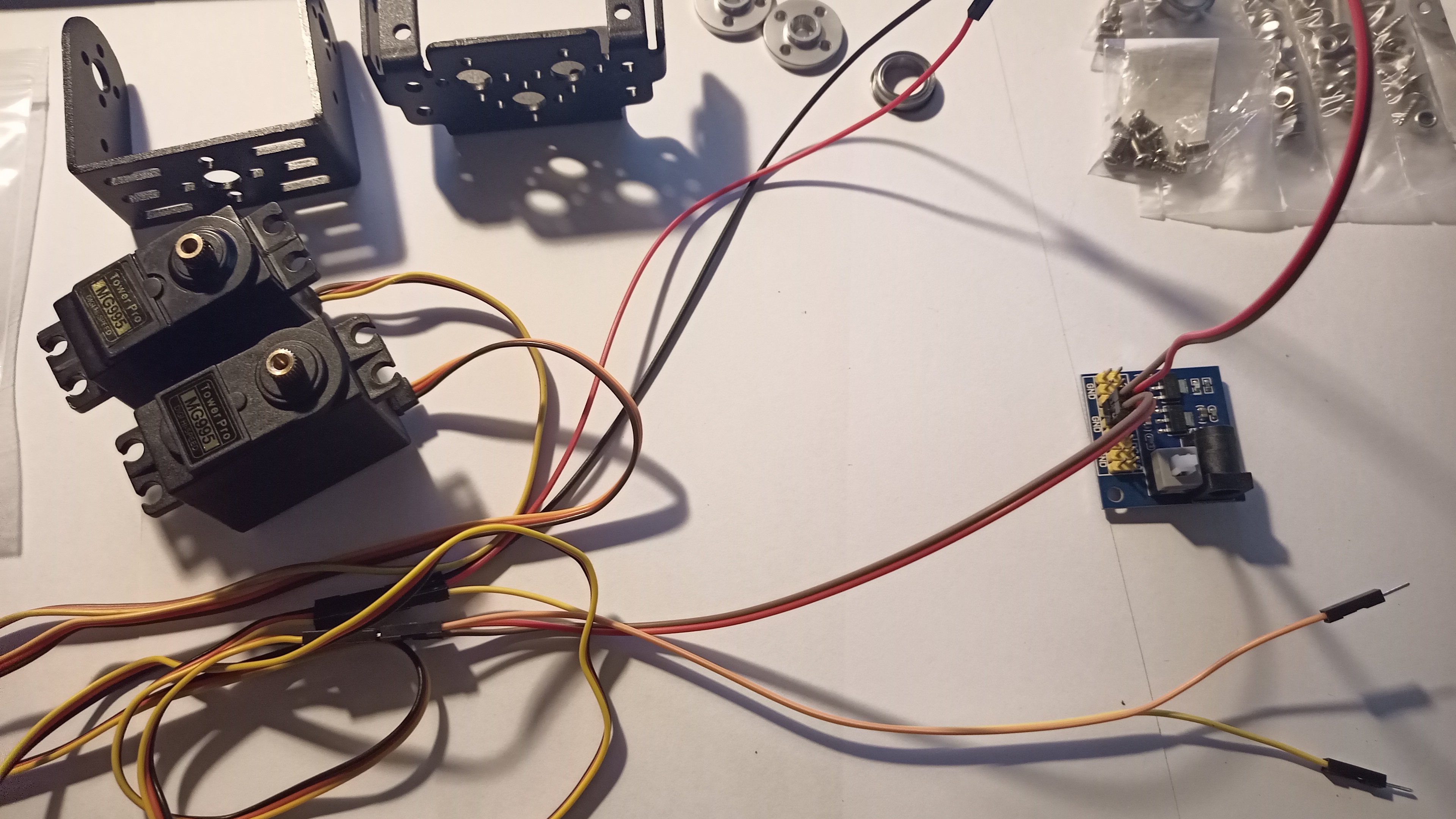
2) Before assembling the servos, set them to the middle position (the mechanism rotated 90 degrees for 180 degree servos). Connect the servo power cables (+5V and GND) to the power module.
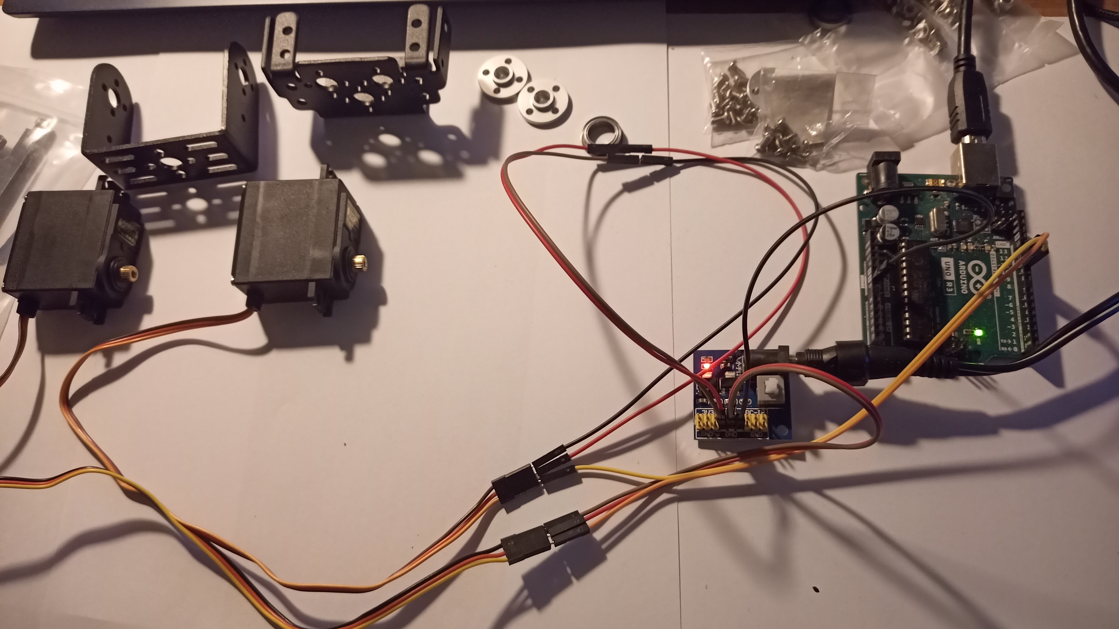
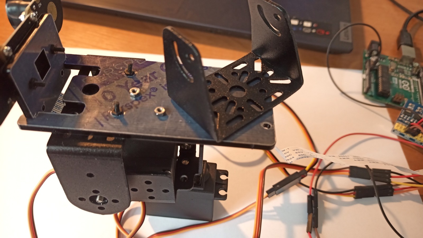
3) To the GND pin on the Arduino (it can be any model - e.g. Uno or Nano) connect the cable with ground (black cable in the picture), the other end of the cable connect to the GND pin of the power module - Arduino and the servo power board must be connected to common ground. On the Arduino, use the Arduino IDE to upload the C++ code from the software available in the Download section (it will be available in the "Client / Arduino" directory). After uploading the code to the Arduino, connect the control wires (PWM) from the servos to it. Yellow cable (pictured) connect to pin 10 on Arduino, orange cable (pictured) connect to pin 11. Pins 10 and 11 on Arduino can generate PWM signal to control servos. With the Arduino connected to the power supply (e.g. to the USB port), press the RESET button on its board. The code uploaded to the board after resetting the board will set both servos in the default position of 90 degrees. For convenience, you can connect the servo cables via extension cables.
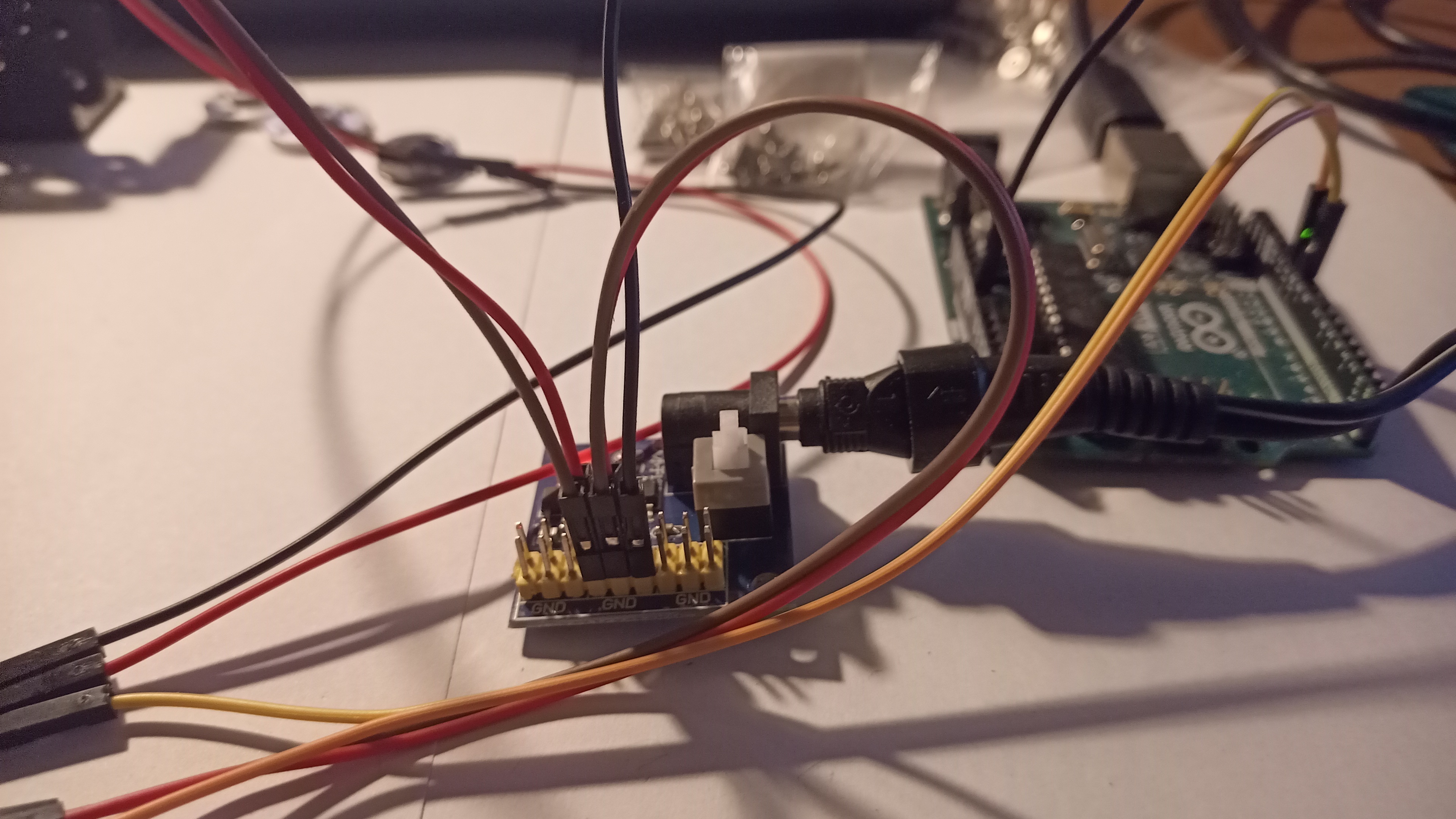
4) Close-up view of the connections on the power board. The red +5V power wires from the servos must be connected to the 5V pins, the black wires - with ground - to the GND pins, an additional ground wire must connect the GND pin on the power board with the GND pin on the Arduino.
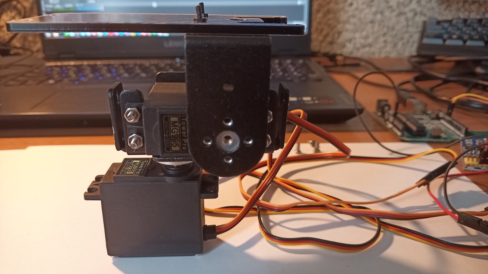
5) With the servos set in 90-degree positions, prepare the lower part of the servo attachment and from its bottom, put an aluminum round horn on it (as in the picture). The drag bar will be the mount for the servo. To screw it to the mount, you will need 4 screws, an additional 5th screw will be needed to screw the round horn to the servo rack.
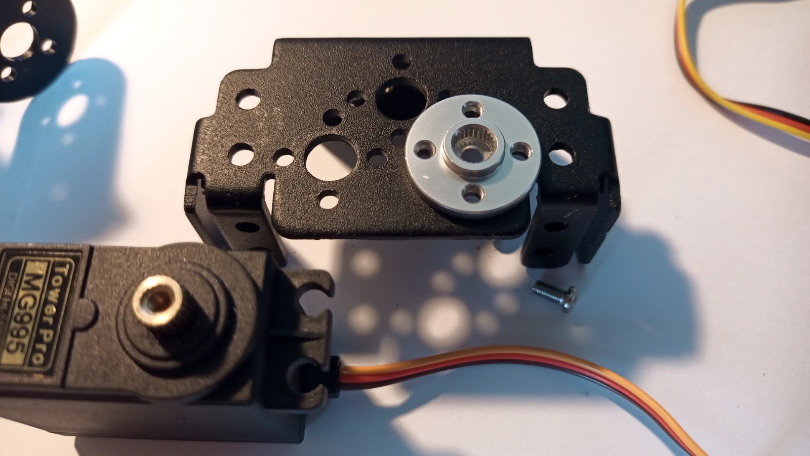
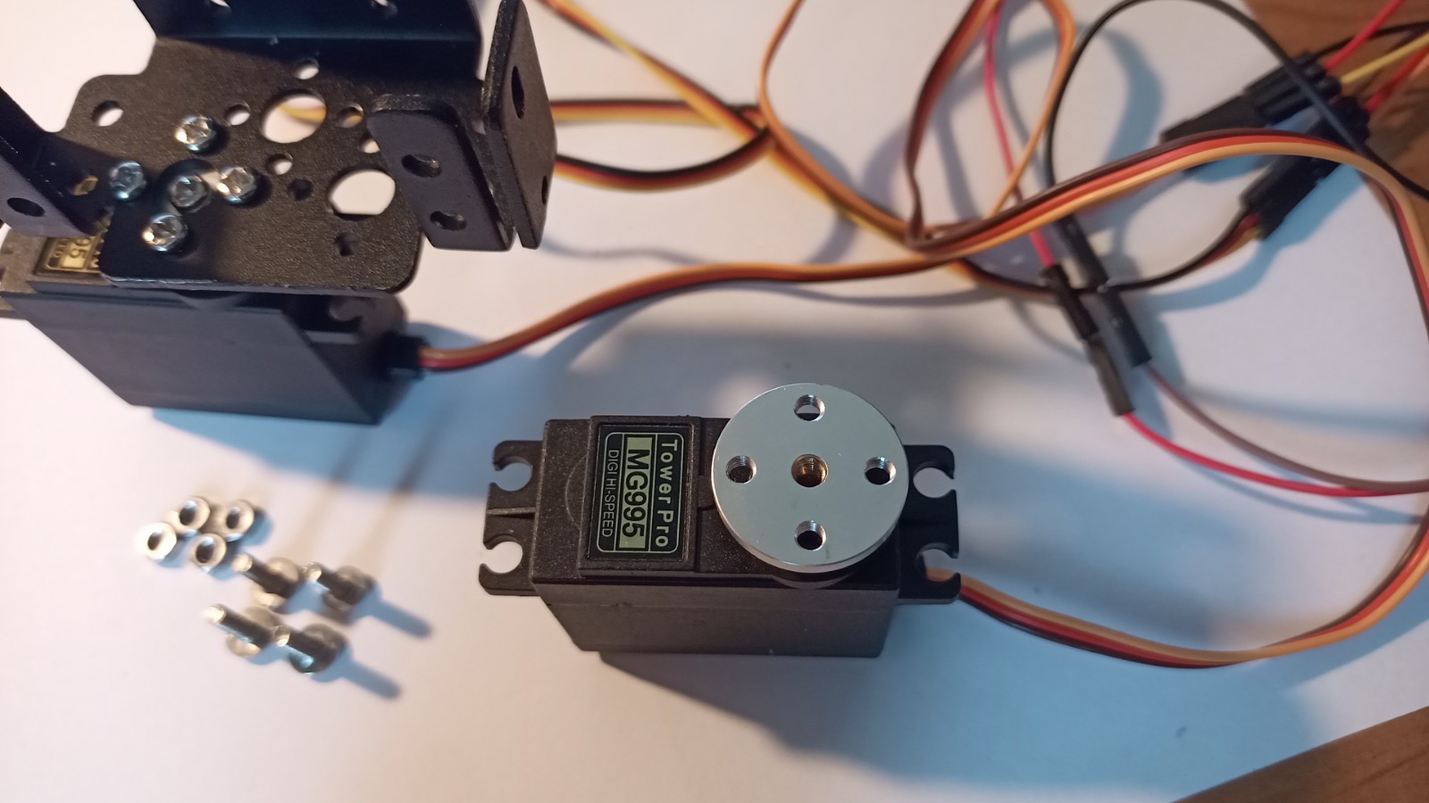
6) A view of the lower servo mount with screws, next to it there is a round horn attached to the servo gears - the screws from the mount will be placed on the round horn in the next step.
7) Put the mount and screws on the round horn placed on the racks, so that the screws match the holes and the servo is set in the position as below.
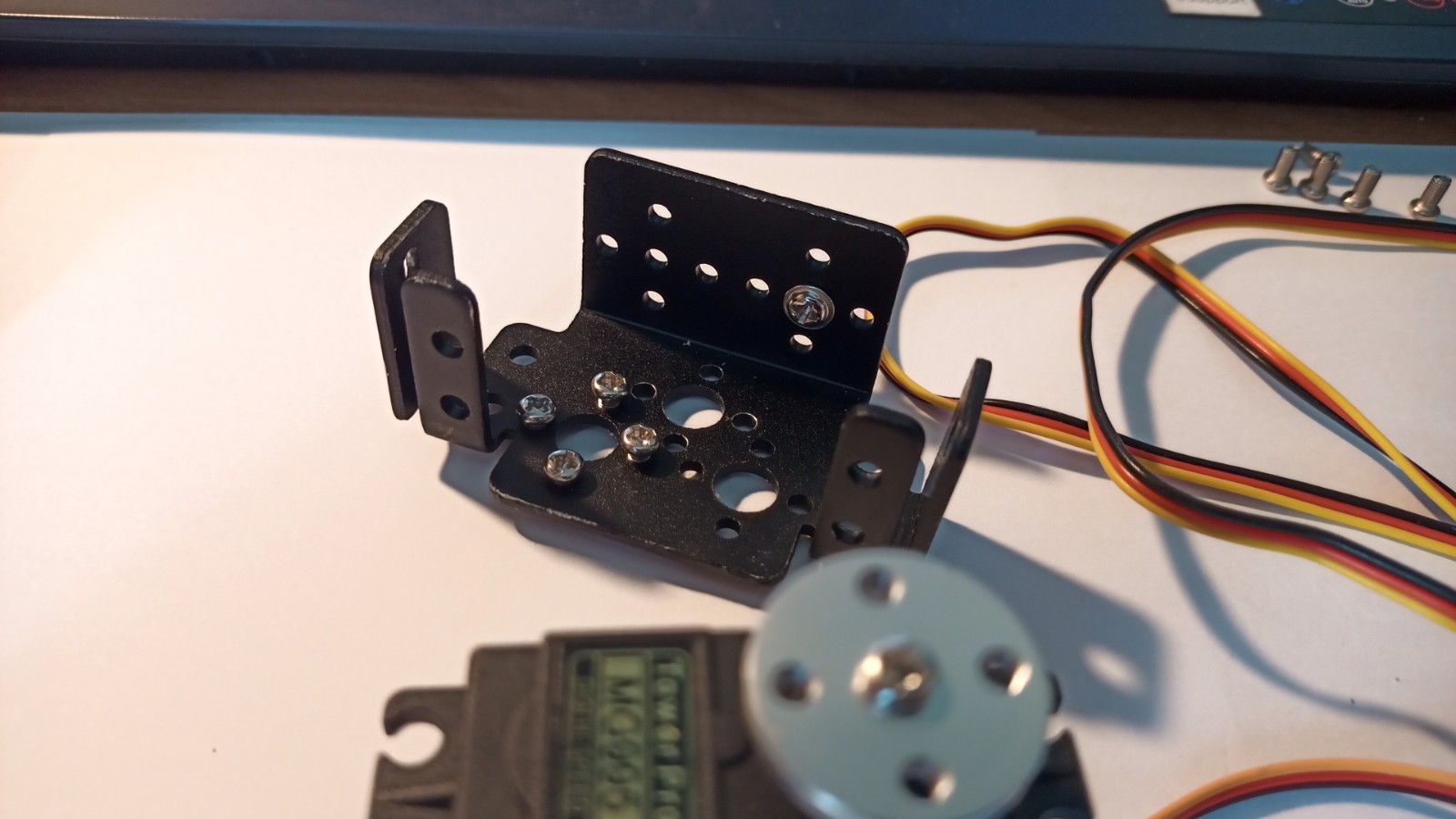
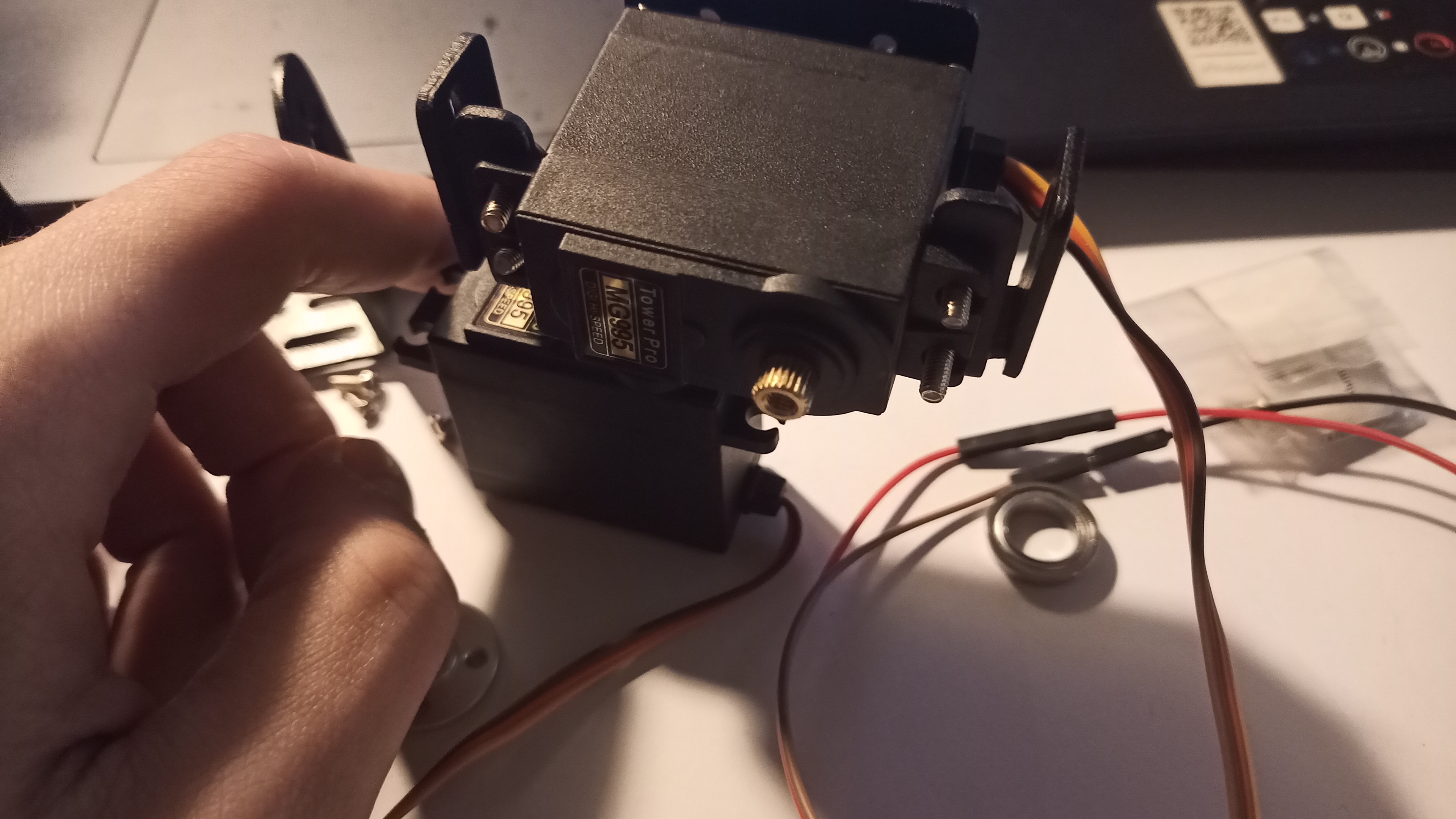
8) Having properly applied the mount and the horn on the sprocket, screw the horn to the sprocket from above using the fifth, middle screw as in the picture below. Note the screw that has appeared on the side to the right of the mount - it will be tightened in the next steps.
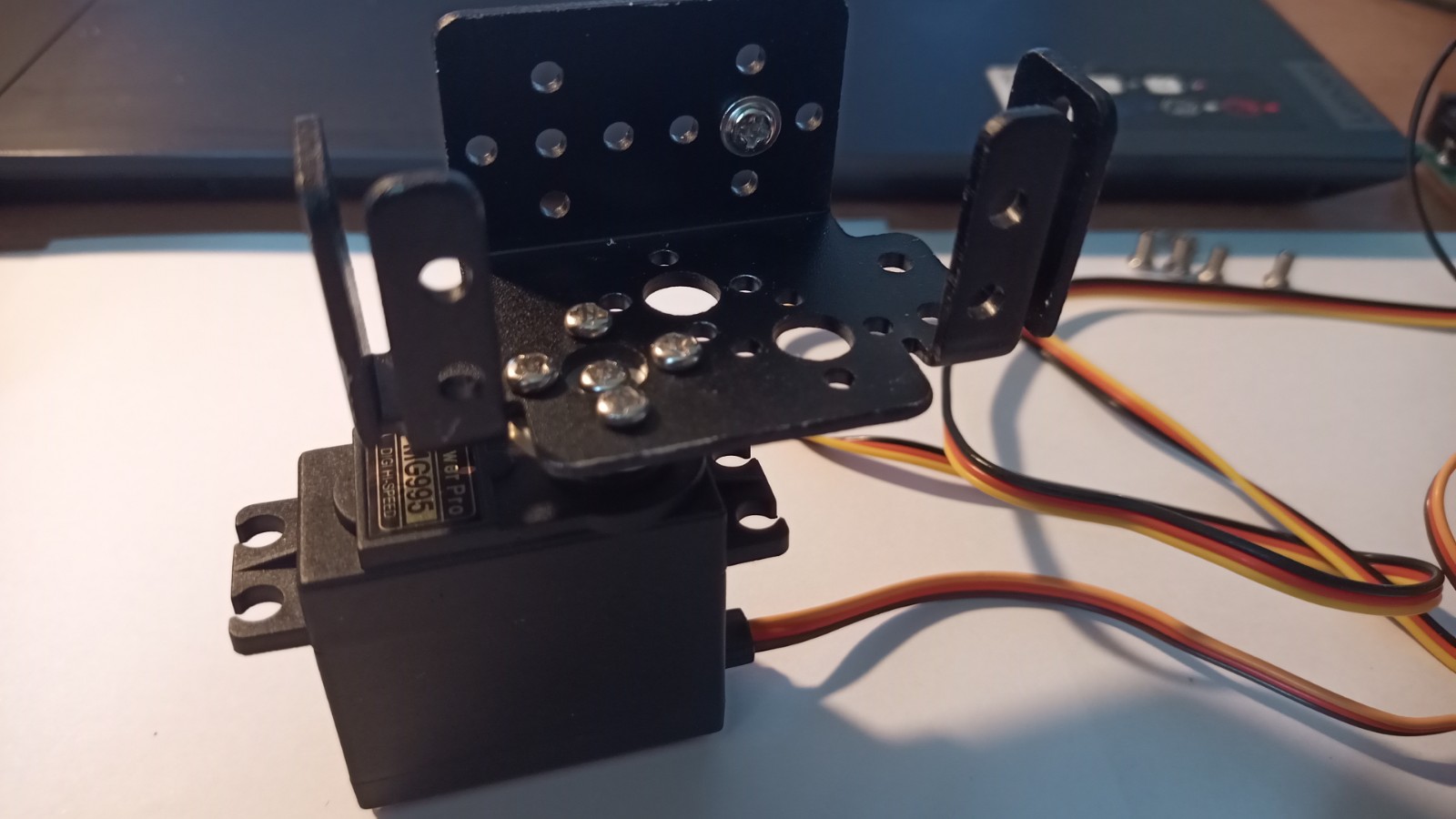
9) Below is a view of the lower mount correctly applied and screwed to the servo.
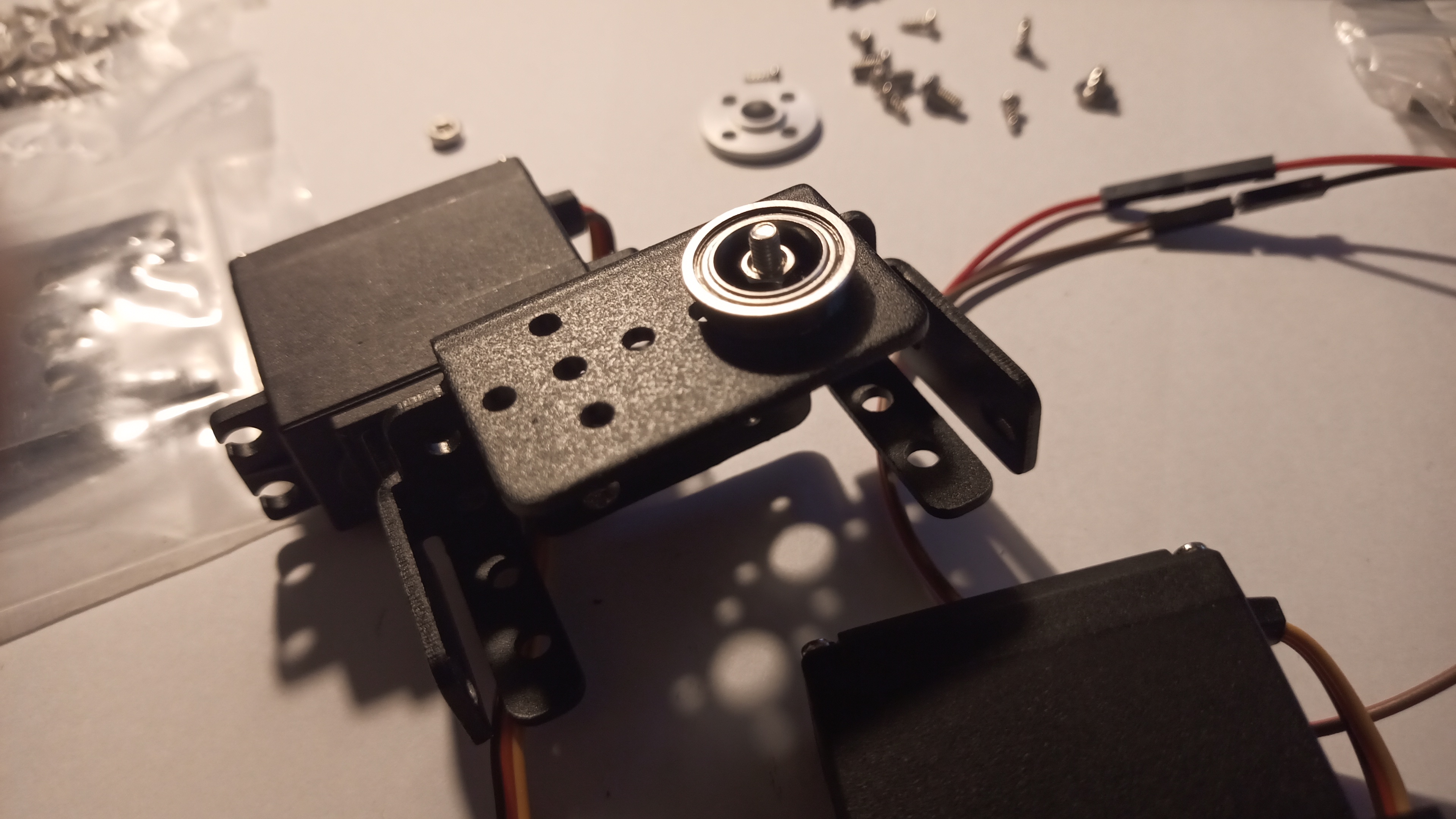
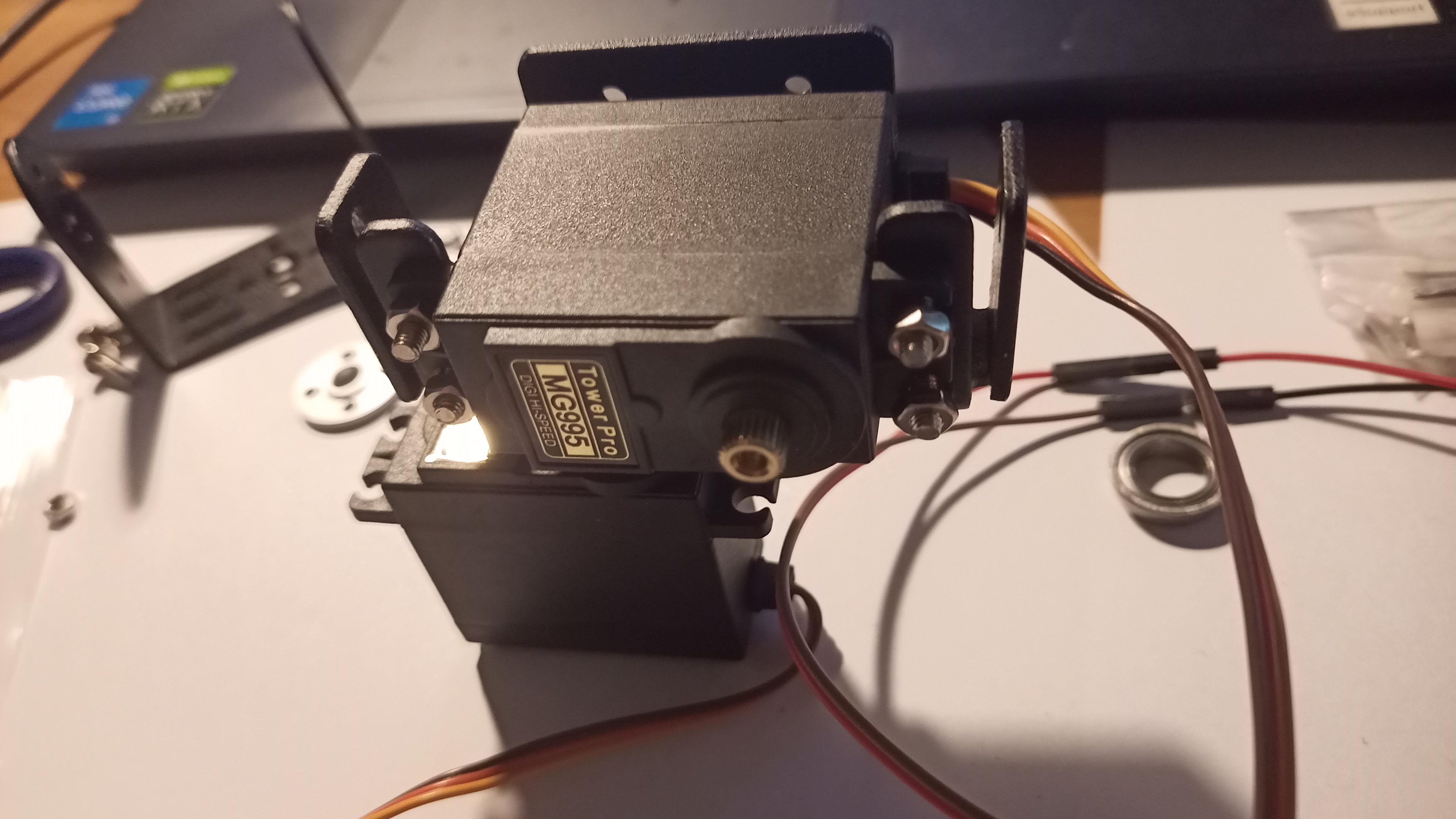
10) On the side of the lower mount (opposite from the servo) from the inside, put the screw visible in the previous photos, and then from the outside, put the round ring as in the picture below.
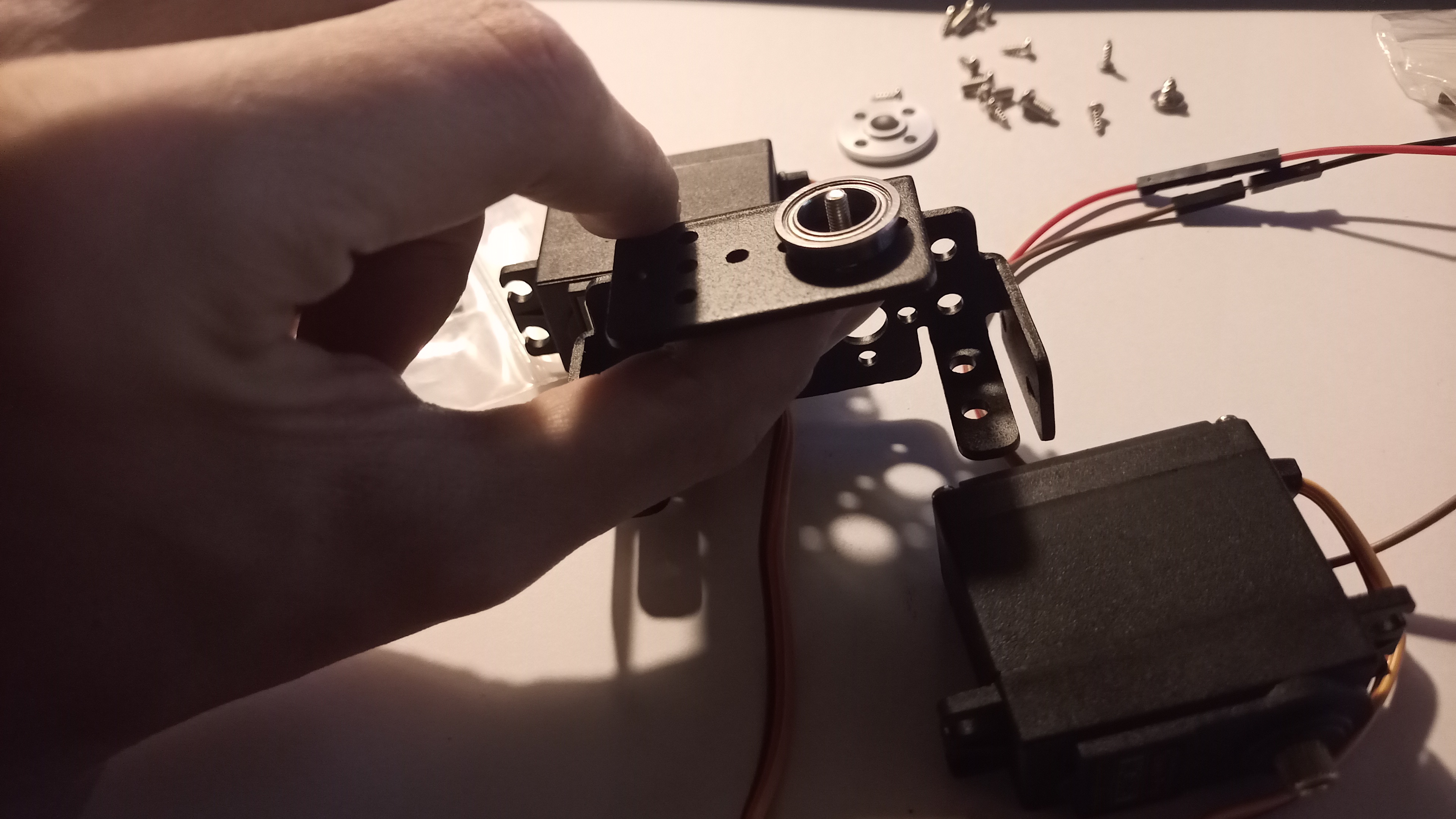
11) Put a nut on the screw from the outside and screw it to the fixing. The bolt and nut will prevent the cap from slipping out once the top of the mount has been applied.
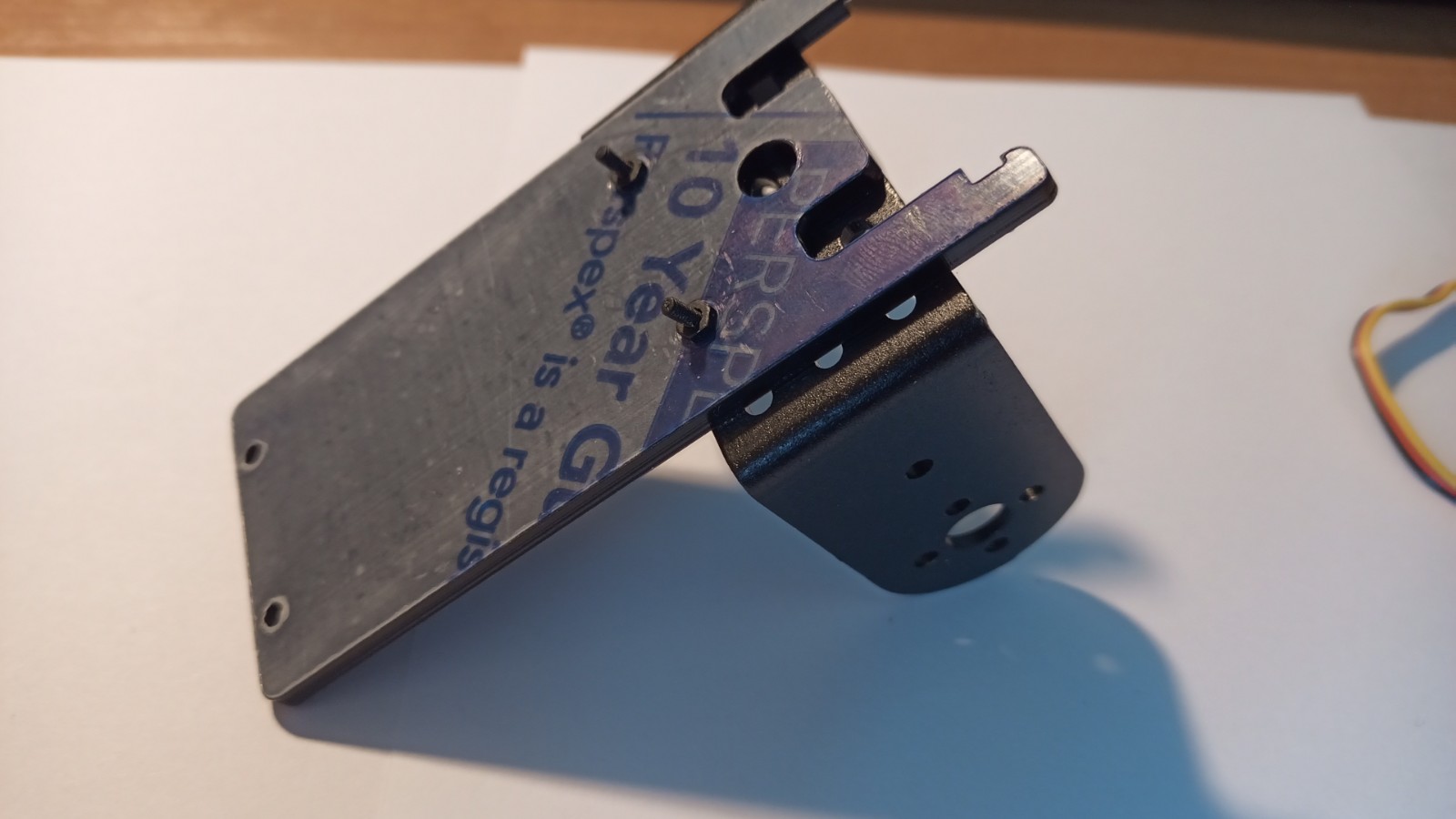
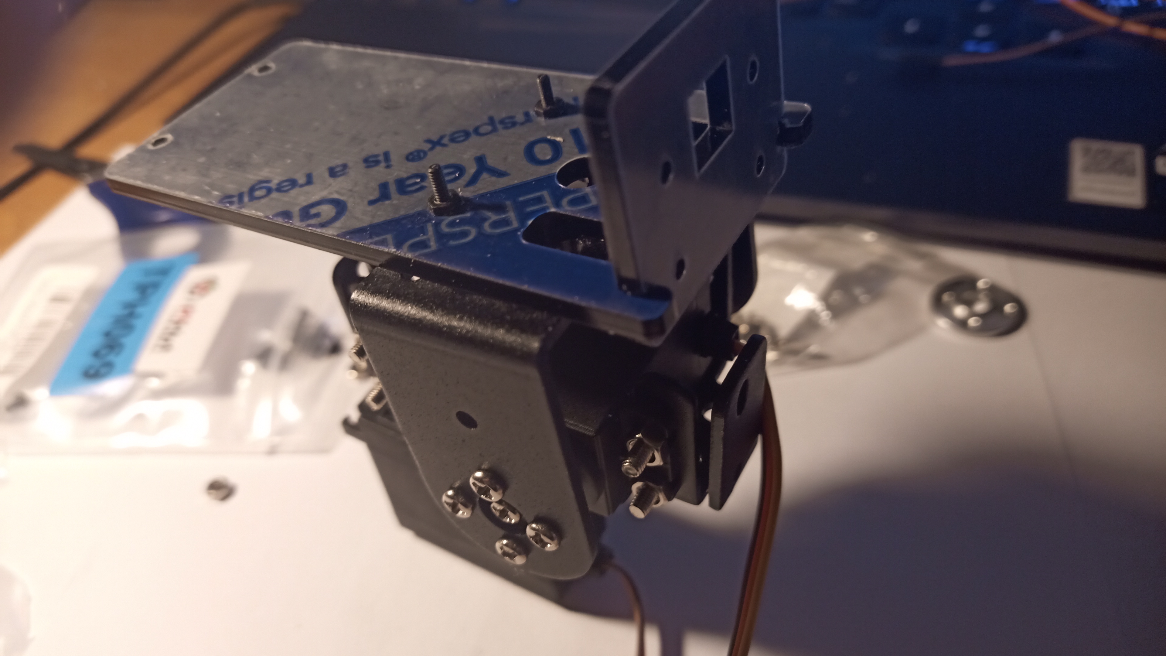
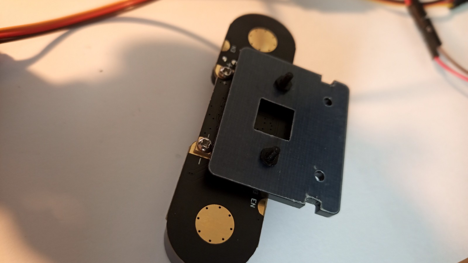
12) Prepare the top of the servo mount and fix the camera mount to it with two screws and two nuts as below.
13) Insert the 4 screws from the inside into the lower part of the servo mount - in a moment you will have to put the holes on the edges of the servo on them from the outside.

14) Put the upper servo in the position as below, aligning the holes of the servo with the screws previously inserted into the mount.
15) Screw all 4 screws from the outside with nuts, thus securing the upper servo.
16) Put an aluminum round horn on the upper servo, in a moment you will put on it and screw the upper part of the mount.
17) Apply the upper part of the fastener from above, starting the application as below.
18) Place the upper part of the mount on the round horn (and on the cover on the other side), in the position as below. Align the top so that the screw holes in the mount match up with the screw holes in the horn.
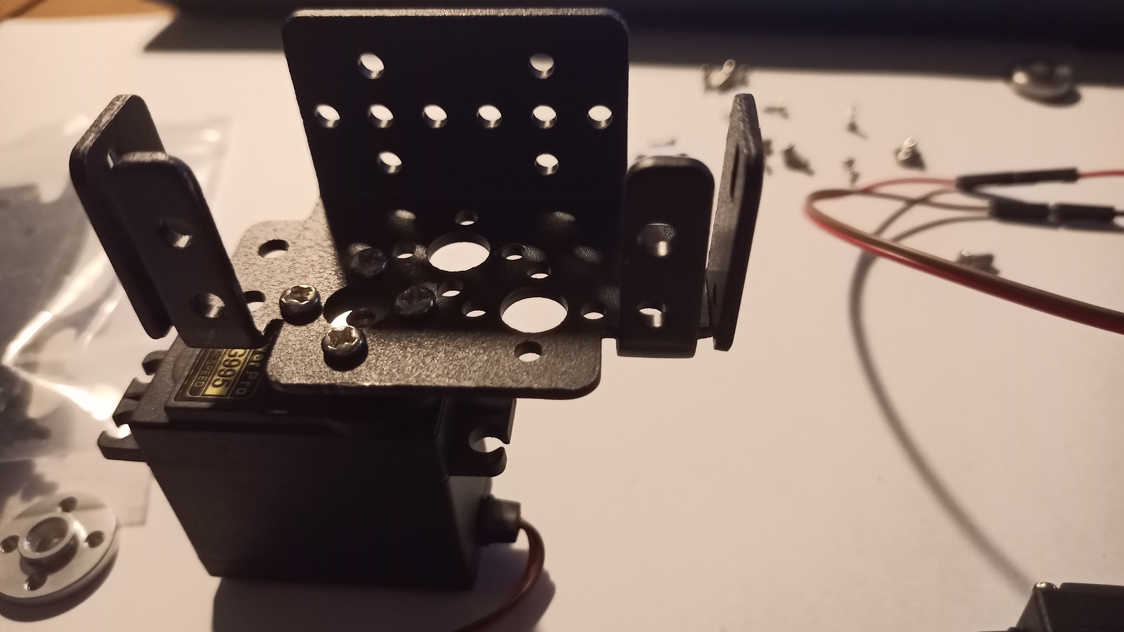
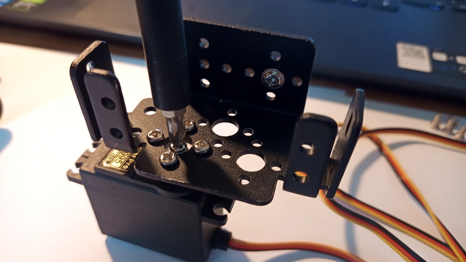
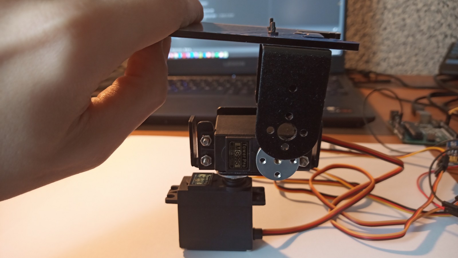
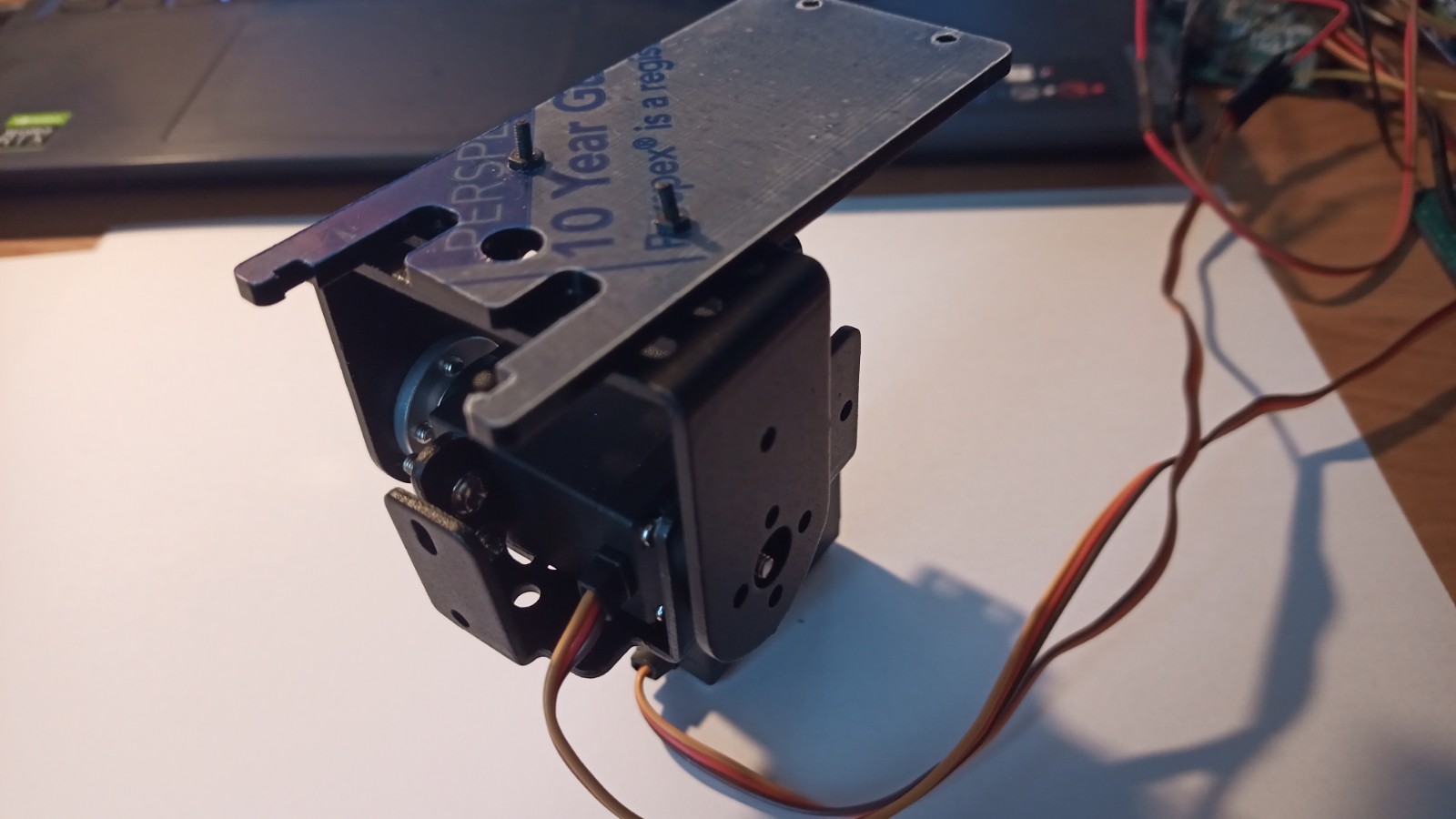
19) Insert and tighten the 4 screws securing the servo clamp from the side. Using the 5 screws, screw the bar to the servo rack. Pay attention to the vertical part of the camera mount - do not put it on now, you will be mounting the camera to it in a moment (it will be more convenient separately)
20) Profile view (with the smaller vertical part of the camera mount removed)
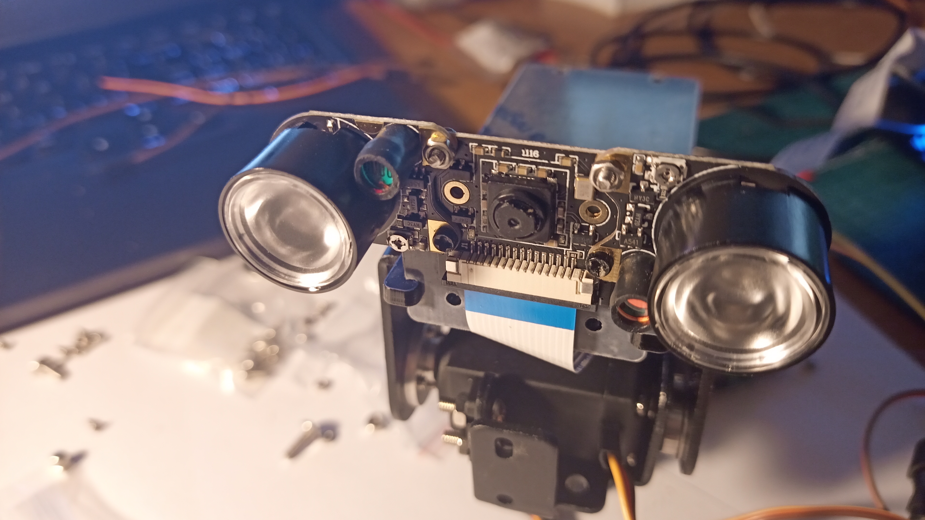
21) Prepare the camera, on the sides of the camera plate, put the side IR reflectors on the camera plate, and fix the reflectors with the top 2 screws and 2 nuts as below. Insert two more longer screws from the outside to the outside into the bottom holes on the camera plate and use them to attach the camera to the vertical mount (shown in photo 19), screwing 2 nuts on the screws on the other side.
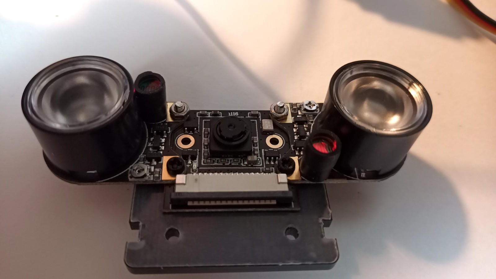
22) Rear view of the board with the camera screwed to the mount (note the + / - markings on the back of the board).
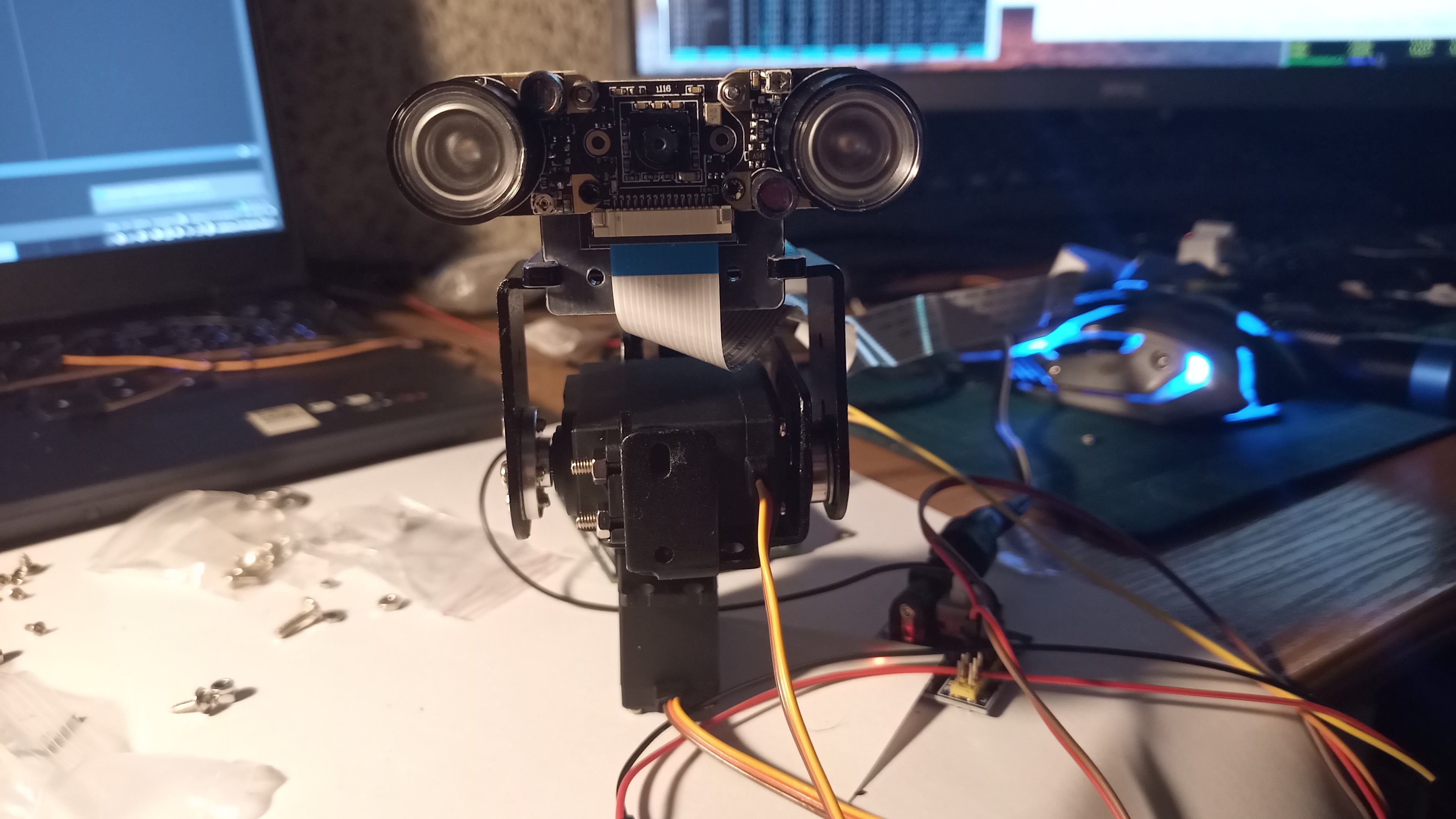
23) Then, put the camera with the screwed mount on the longitudinal part of the camera mount previously mounted. Connect a 60cm tape (or longer if you have one) to the camera. The blue part of the tape should face the front of the camera as shown in the picture. Then pull the tape under the upper servo mount and connect the other part to the CSI connector on the Raspberry main board.
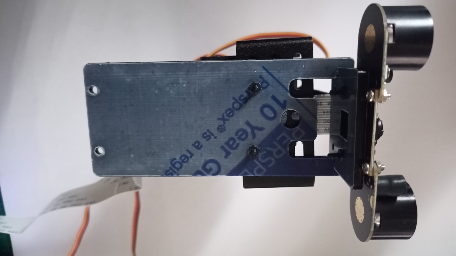
24) Rear view.
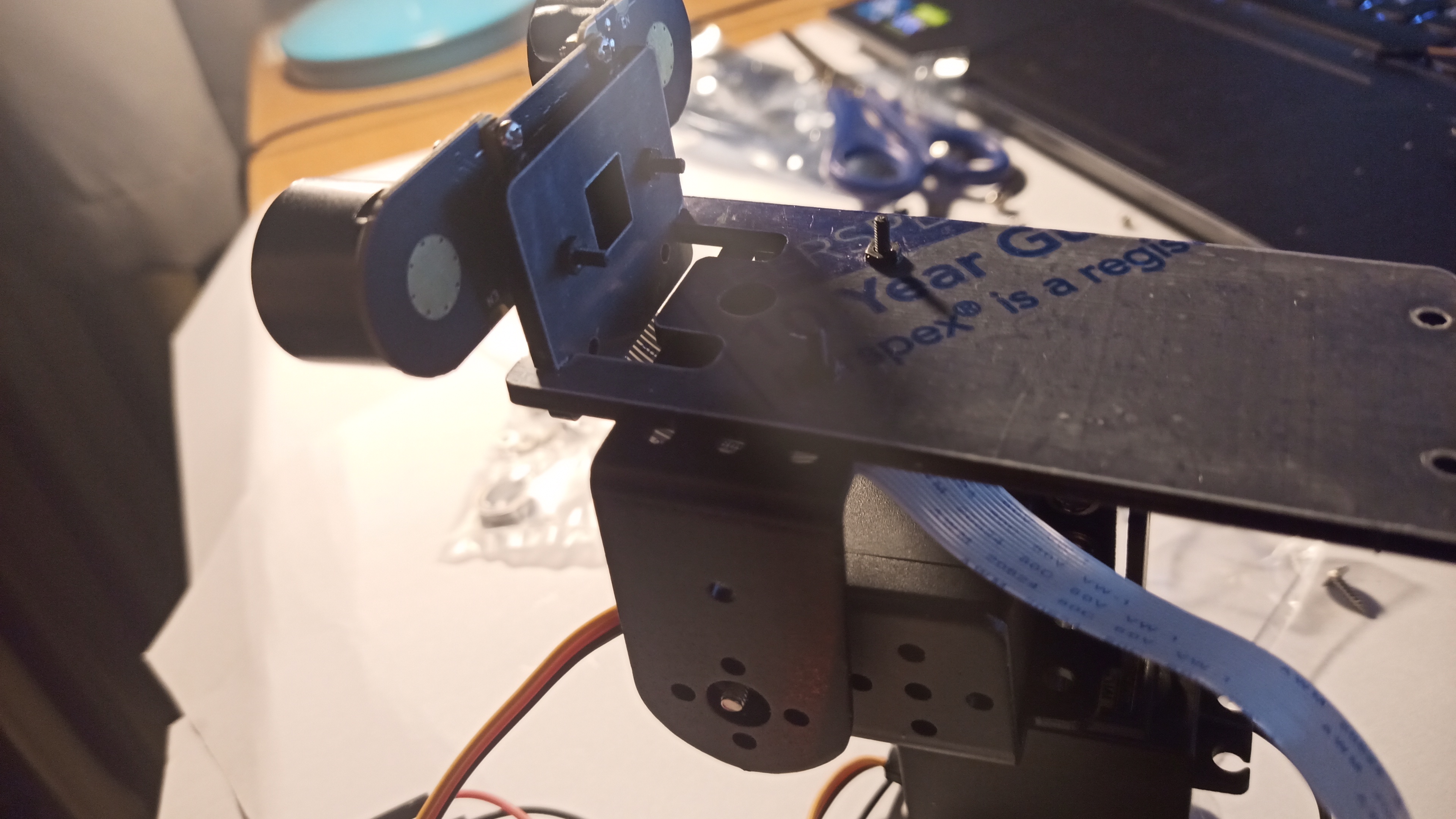
25) Top view
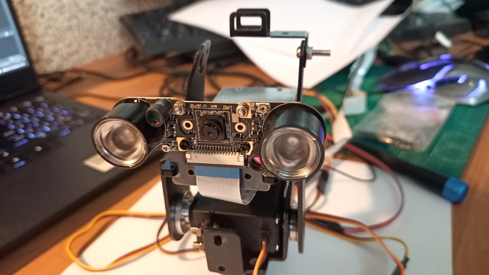
26) Front view.
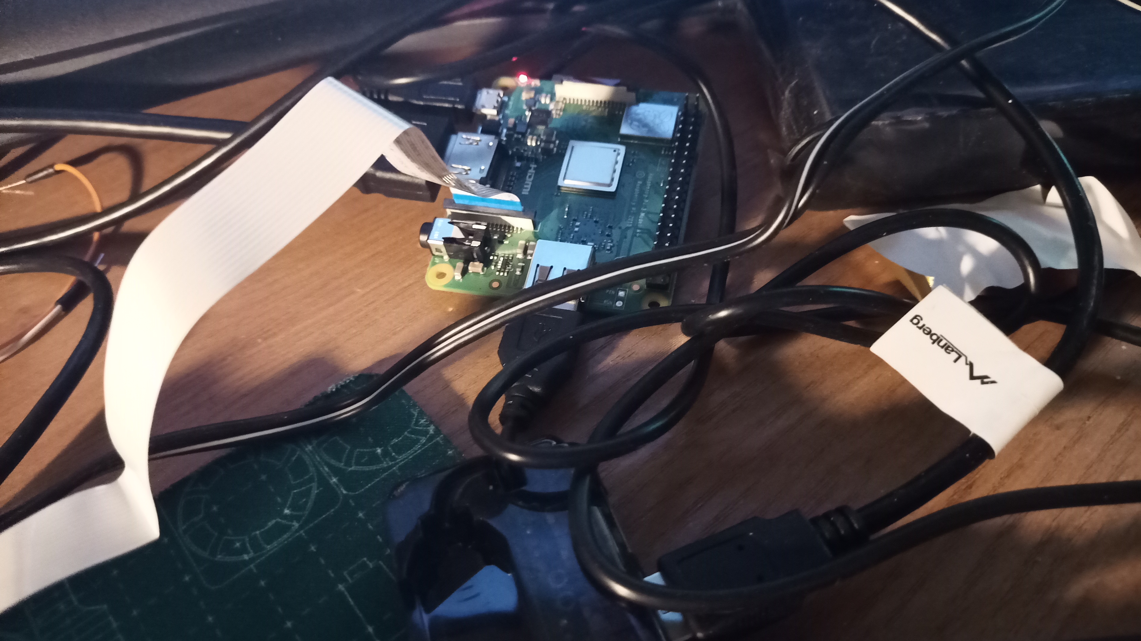
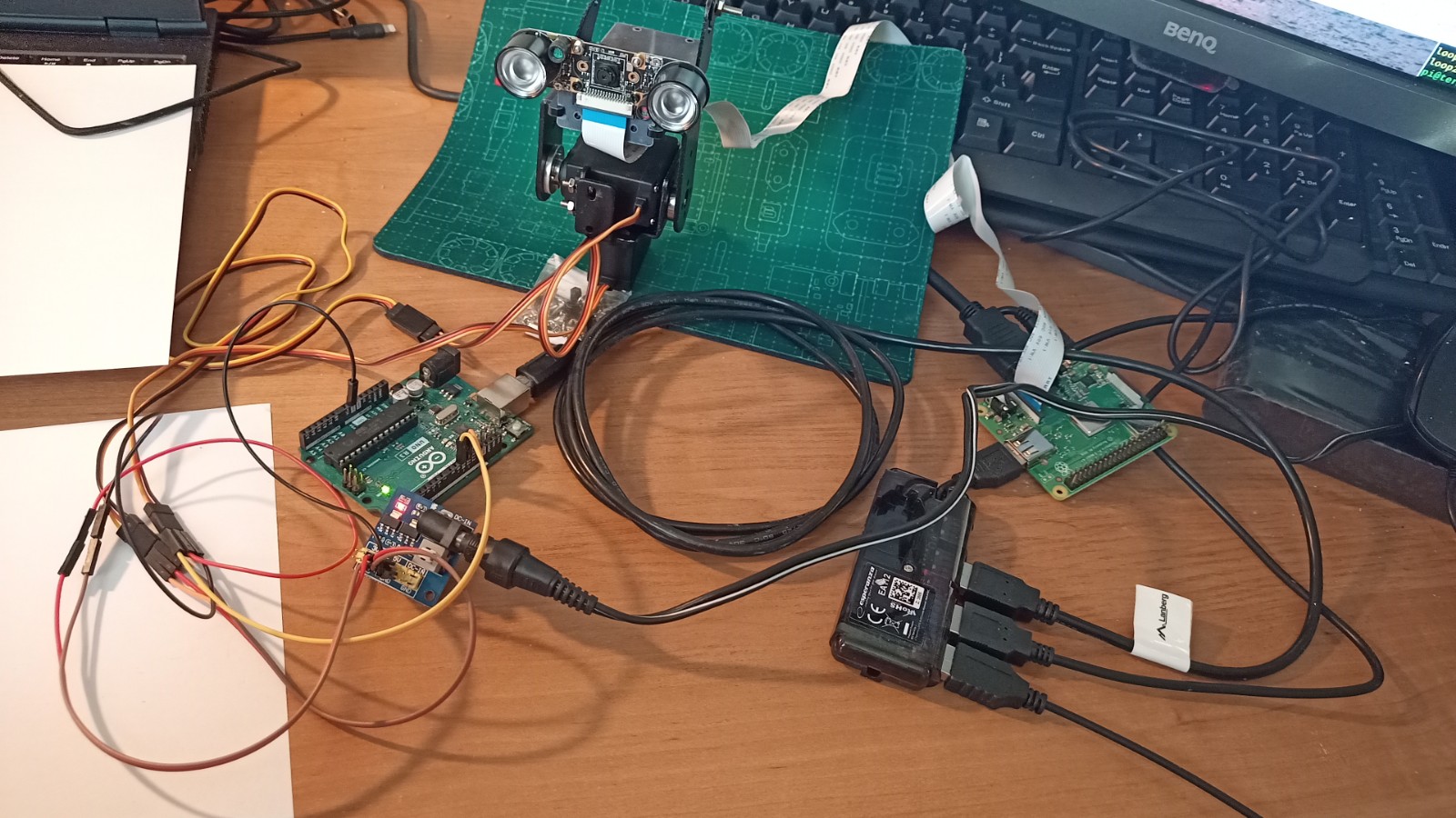
27) View of the connected CSI tape running from the camera to the Raspberry motherboard (pictured is a Raspberry Pi 3 model A+, but you can use any model here). Connect the USB HUB to the USB connector on the Raspberry, and then connect the Arduino to the HUB using the USB cable. The blue part of the tape should face as in the picture.
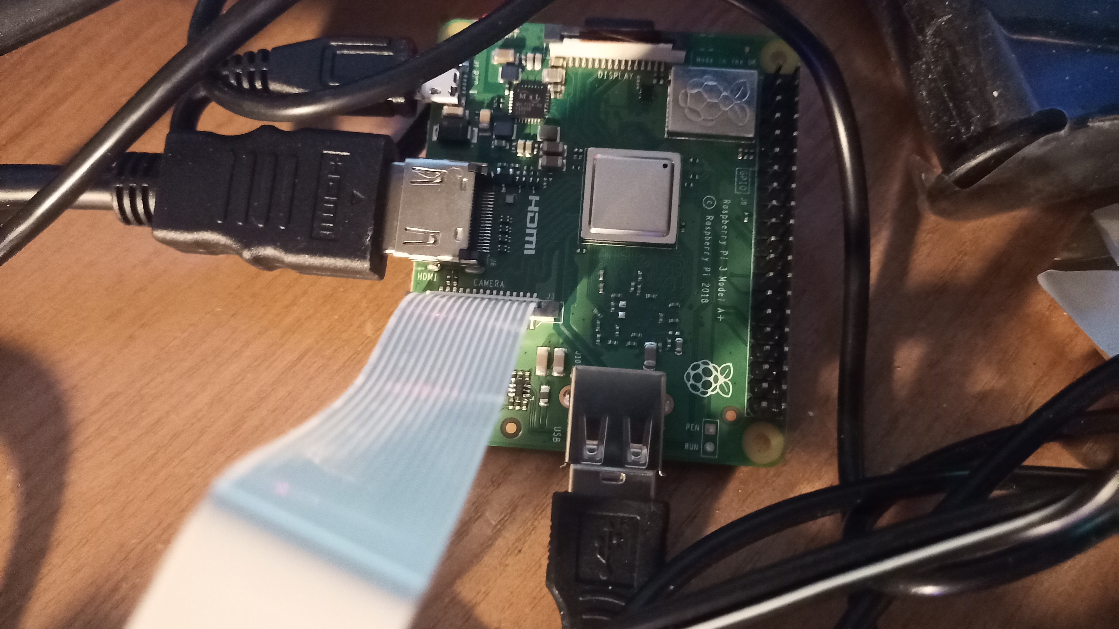
28) A close-up view of the Raspberry motherboard. From the bottom, a HUB connected to 4 USB ports, to which the Arduino is then connected. From the left, the HDMI cable from the monitor is connected and on the top left +5V power supply using a power supply with a microUSB output. The ribbon from the camera is connected to the CSI connector.
29) Optionally, you can mount an additional mount on the upper camera mount (for example, to mount something on top, e.g. a laser).
30) Screw the upper fastening to the already emerging bolts with nuts.
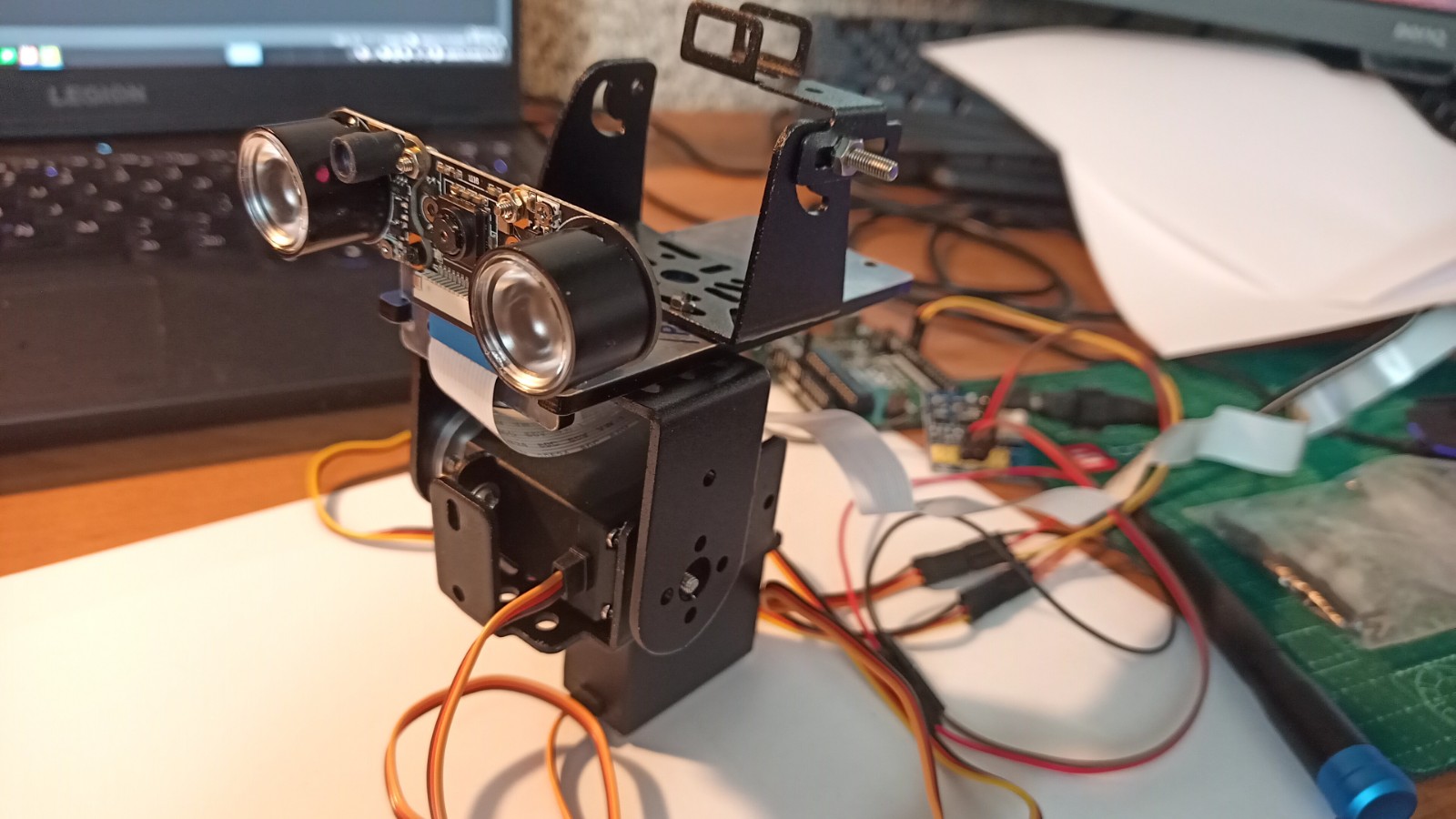
31) Ready ;)
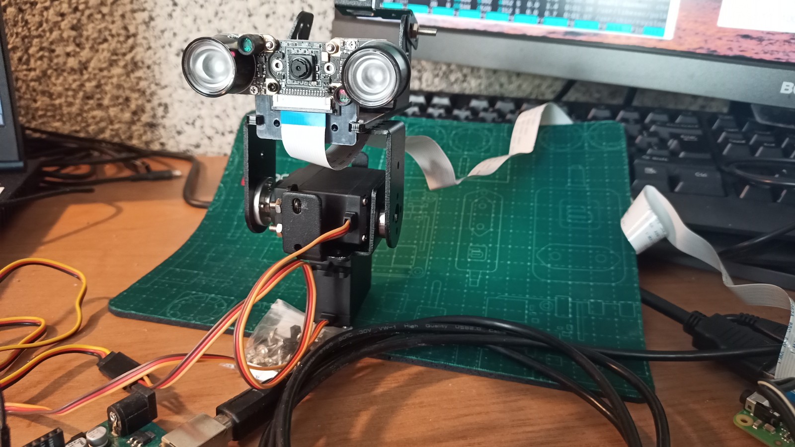
32) View of the whole machine.
33) A close-up view of the whole thing.
SOFTWARE
The example project presented above allows for remote control (via WiFi network) using Raspberry and Arduino. However, there are more connection options, including local connection via USB ports - all possible connection configurations can be found in the available documentation. Below is a brief description of further steps when using the connection option shown in the photos:
- upload the latest version of the Rasbian system on the Raspberry, you can use an SD card reader for this - insert the SD card into the reader, download the ImageWriter program and use it to upload the latest version of the Rasbian system to the SD card.
- remove the card from the reader and insert it into the Raspberry, then connect the monitor to the Raspberry using HDMI, and the keyboard and mouse using the USB hub. Connect the power supply to the Raspberry using a 5V power supply with a micro USB connector.
- start the Raspberry and finish the system installation on the SD card by creating a new user in the system and configuring the WiFi network.
- after installing the system, increase the size of the swap file to 1GB - details can be found in documentation.
- using a USB hub, connect the Raspberry to the Arduino and upload the client software available in Download page - details of installation, connection between devices, usage and full configuration can be found in documentation.
The documentation is available in 2 languages: English and Polish.
Full software used to control the whole can be downloaded from here: Download.
Link to full, up-to-date documentation with further instructions:
Full software used to control the whole can be downloaded from here: Download.
The software is available for Windows and Linux systems, for PC, Raspberry and Arduino platforms.
Source code is available on GitHub.
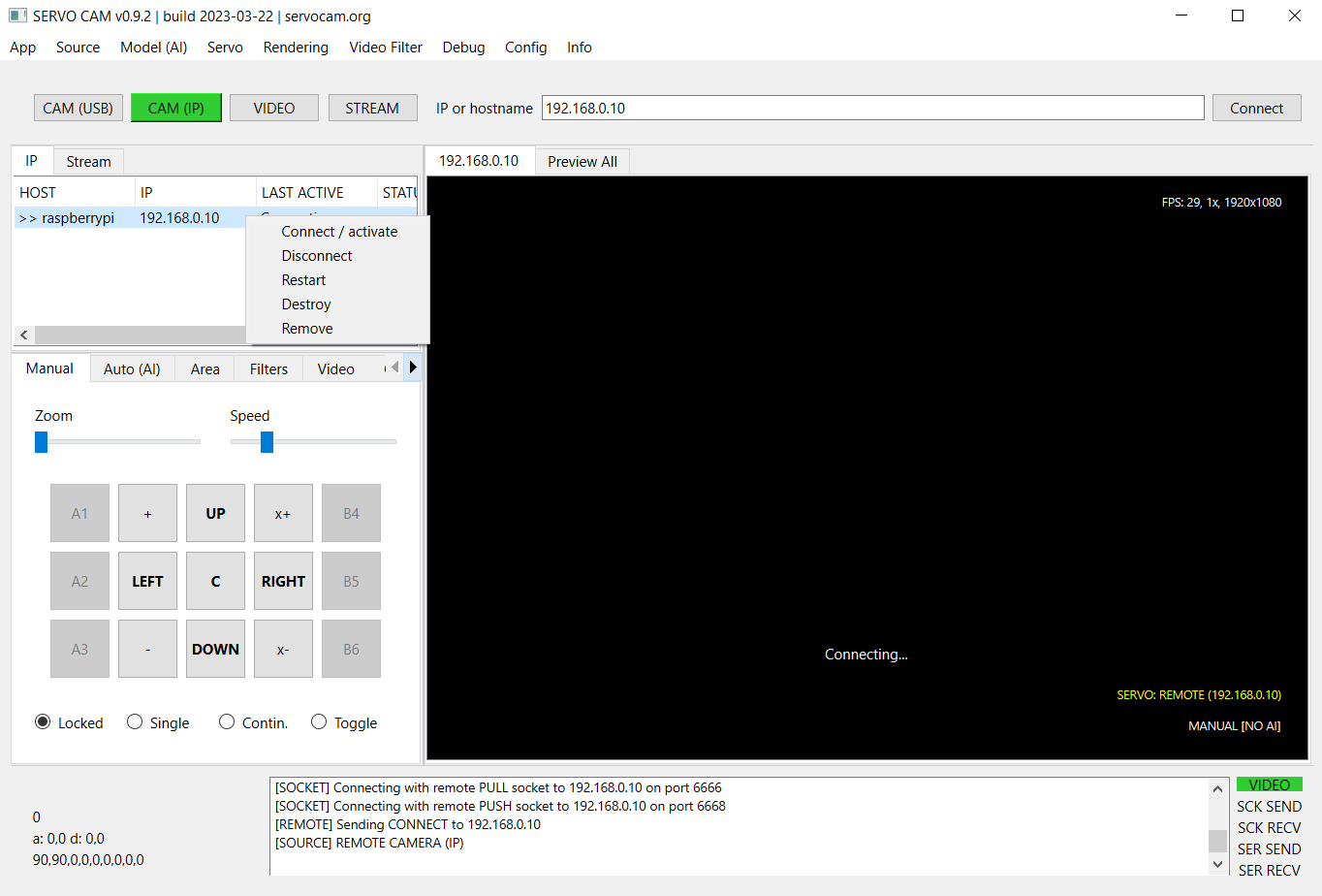
Screenshot of desktop server application (Windows 10):
WANT TO ASK, DONATE OR SUPPORT?
Contact